
Plan the investigation
Choose the system and the reference point
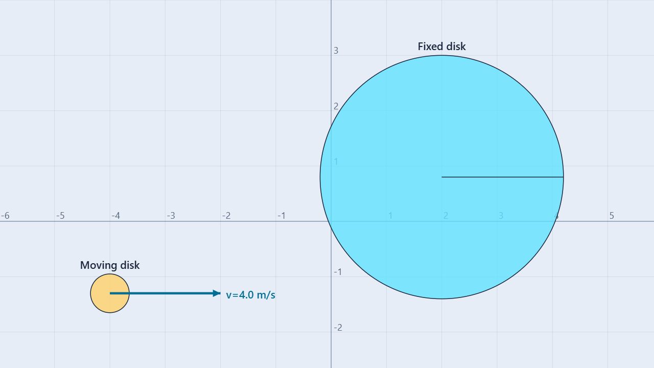
The prepared scene has a 10.0 kg, 2.20 m radius target disk centered at (2.00 m, 0.80 m). A 1.00 kg, 0.35 m radius disk moves right at 4.00 m/s along y = −1.30 m. The target’s center is fixed so it cannot translate, but it can rotate. The collision is set to be completely inelastic so the moving disk transfers angular momentum into the target system.
Keep fixed
Target center, disk masses and radii, incoming speed, gravity set to zero, and the system boundary containing both disks.
Change one variable
Move the incoming disk vertically to change the impact parameter. Keep its speed and direction fixed for the first comparison.
Use the large disk’s center as the origin. During the brief collision, external torque about that point is negligible: gravity is off, the support acts through the chosen center, and contact forces between the disks are internal to the two-disk system.
Build the model
Add orbital and spin angular momentum
For a particle or disk center moving in a straight line, angular momentum about the chosen origin is the cross product Lorb = r × p. In this horizontal-motion setup, only the perpendicular impact parameter b matters:
Lorb,z = −bmvx
A spinning rigid disk contributes Lspin = Iω. For a solid disk, I = ½MR². The conservation condition is:
ΣLinitial = ΣLfinal
when ∫τexternal,zdt ≈ 0
Before impact, the moving disk has orbital angular momentum and zero spin. After an off-center, inelastic impact, angular momentum can be shared between the target’s spin, the incoming disk’s spin, and any remaining orbital motion. The total about the chosen center is the quantity to compare.
Procedure
Measure transfer, not just final spin
- Load and inspect. Open Conservation of Angular Momentum. Select the target and moving disks and record their masses, radii, center positions, and initial velocities.
- Mark the origin. Use the large disk’s center as the reference point. Define counterclockwise angular momentum as positive.
- Calculate the baseline. Measure the incoming disk’s vertical offset b = ymoving − ytarget. Calculate Lorb,z = −bmvx and include any initial spin terms.
- Run through contact. Start the collision and let the disks interact. Pause after the transfer is complete, then record target angular velocity, moving-disk angular velocity, and the total angular momentum about the target center.
- Check conservation. Compare the initial and final total values. Separately identify which contribution decreased and which spin contribution increased.
- Change the impact point. Reset and move the incoming disk vertically to create new impact parameters. Keep its speed and the target unchanged, then repeat the calculation and collision.
| Quantity | Calculation | Prediction |
|---|---|---|
| Impact parameter | b = −1.30 − 0.80 | −2.10 m |
| Initial orbital angular momentum | −(−2.10)(1.00)(4.00) | +8.40 kg·m²/s |
| Initial spin angular momentum | Iω = 0 for both disks | 0 kg·m²/s |
| Initial total | Lorb + Lspin | +8.40 kg·m²/s |
| Target-disk inertia | ½(10.0)(2.20²) | 24.2 kg·m² |
The simulation may report small differences because the contact is resolved numerically. Use a single paused frame for all final contributions.
Worked example
Predict the sign before impact
The moving disk travels right below the chosen origin, so its radius vector points down while its momentum points right. That combination produces positive, counterclockwise angular momentum:
Lorb,z = x py − y px
= 0 − (−2.10)(1.00)(4.00)
= +8.40 kg·m²/s
If the moving disk remains attached at the target rim, an ideal combined-body estimate uses the target’s inertia plus the incoming disk’s parallel-axis inertia:
Icombined = 24.2 + [½(1.00)(0.35²) + 1.00(2.55²)]
≈ 30.72 kg·m²
ωideal = 8.40/30.72 ≈ +0.274 rad/s
Treat this as a model check. The measured final value depends on the exact contact geometry and whether the incoming disk remains locked to the target in the resolved collision.
Compare trials
Use impact parameter to control L
Keep m = 1.00 kg and vx = 4.00 m/s fixed. Moving the incoming disk vertically changes the perpendicular offset and therefore the initial orbital angular momentum without changing its speed.
| Incoming center y (m) | Impact parameter b (m) | Initial Lorb,z (kg·m²/s) | Prediction |
|---|---|---|---|
| −1.30 | −2.10 | +8.40 | Counterclockwise transfer |
| −0.30 | −1.10 | +4.40 | Smaller positive spin |
| +0.80 | 0.00 | 0.00 | Central impact; no initial orbital L |
| +1.80 | +1.00 | −4.00 | Clockwise transfer |
For a central impact, the incoming disk can still exchange linear momentum and kinetic energy, but its orbital angular momentum about the target center is zero. That makes it a useful control trial.
Interpret the evidence
Track contributions and the total
Graph the target’s spin contribution, the incoming disk’s orbital or spin contribution, and their algebraic total about the same origin. Individual contributions may change sharply at contact while the total remains nearly constant.
Ltotal = Lorb,moving + Itargetωtarget + Imovingωmoving
RL = Lfinal − Linitial
A small angular-momentum residual supports the zero-external-torque model. Do not use kinetic energy as the conservation test for this sticking collision:
Kinitial ≠ Kfinal in a perfectly inelastic collision
Common misconceptions
Check the reasoning
Does the moving disk need to spin initially?
No. A translating disk can have orbital angular momentum about an origin when its line of motion has a nonzero perpendicular offset.
Is angular momentum conserved about every point?
No. State the origin and check external torque about that origin. The target center is useful here because support and radial contact forces have no torque about it.
Does a sticking collision conserve kinetic energy?
No. Angular momentum can be conserved while kinetic energy is converted into deformation, heat, and other internal energy.
Does friction destroy angular momentum?
Contact friction transfers angular momentum between the disks. It changes individual contributions, but it does not remove the system total when external torque is negligible.
For teachers
Make the origin and system boundary visible
Require students to mark the target center before calculating. Have them write the two-disk system boundary and explain why contact forces are internal. Ask for signed angular momentum, not just magnitude, so an above-center impact is recognized as clockwise.
Use the four impact-parameter rows as a controlled investigation. Then compare an off-center and central impact while keeping incoming speed fixed. Require students to explain why the off-center trial transfers spin while the central trial has nearly zero initial orbital angular momentum.
Review Newton’s Third Law, Work and Kinetic Energy, and Rotational Inertia Versus Angular Acceleration. Physics reference: OpenStax, University Physics Volume 1, §11.2 Angular Momentum. Learn about the educator behind the simulations on the BuildPhysics About page.