
Plan the investigation
Can a lighter rider balance a heavier rider?
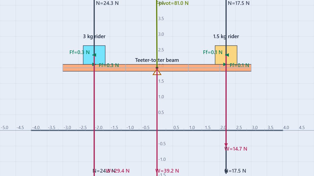
The prepared scene has a 6 m beam with mass 4 kg, a central pivot, a 3 kg rider on the left, and a 1.5 kg rider on the right. Friction is enabled to help riders remain on the beam. The starting arrangement is unbalanced.
Change
Right rider mass: 1, 1.5, 2, 2.5, and 3 kg.
Keep fixed
Left rider at 3 kg and 1 m left of the pivot; right rider 2 m right of the pivot. Keep the beam horizontal initially, with zero angular velocity and the original central pivot.
Reset and reposition the riders for this investigation rather than using the original distances. Measure horizontal center positions relative to the pivot. The rider labels may retain their original mass names after you edit Mass; use the numerical property.
Build the model
Choose a torque sign convention
Take counterclockwise torque as positive. A downward force left of the pivot gives positive torque; a downward force right of it gives negative torque.
τ = Fd⊥
Στ = mLgdL − mRgdR
Here d is the horizontal distance from the pivot to the vertical line through a rider’s center. The beam’s own weight acts at its center, directly over the central pivot, so it contributes zero gravitational torque in this setup. The pivot force also has zero lever arm about the pivot.
Balance: mLdL = mRdR
These are initial horizontal-beam predictions. Once the beam tilts, rider positions and contact forces can change. Use the initial tendency to turn rather than a later impact with the ground to judge your prediction.
Procedure
A useful five-trial workflow
- Load and inspect. Launch the simulation and choose the Teeter-totter experiment if a saved scene appears. Keep gravity downward at 9.80 m/s² and friction enabled.
- Arrange the riders. While reset, place the 3 kg left rider with its center at x = −1 m and the right rider at x = +2 m, supported on the horizontal beam. The pivot remains at x = 0. Check their actual center positions after placement.
- Set and predict. In Properties, set the right rider’s mass to 1 kg. Keep left mass at 3 kg. Calculate both gravitational torques and their signed sum.
- Run briefly. Start from zero velocity and angular velocity. Use a 0.5-second run duration beside Play. Observe which side initially descends, or whether the beam remains approximately level. Stop before riders slide off or the beam reaches the ground.
- Reset and repeat. Reset before entering 1.5, 2, 2.5, and 3 kg for the right rider. Restore the same horizontal beam and rider positions. Record mass, measured lever arms, predicted torque, and observed initial turning direction.
| Right mass (kg) | Left torque (N·m) | Right torque (N·m) | Net torque (N·m) | Prediction |
|---|---|---|---|---|
| 1.0 | +29.40 | −19.60 | +9.80 | Left descends |
| 1.5 | +29.40 | −29.40 | 0.00 | Balanced |
| 2.0 | +29.40 | −39.20 | −9.80 | Right descends |
| 2.5 | +29.40 | −49.00 | −19.60 | Right descends |
| 3.0 | +29.40 | −58.80 | −29.40 | Right descends |
Small placement differences can create residual torque in the balanced trial. Check lever arms before changing masses to compensate. The preset includes beam damping, so it is better suited to balance and turning-direction comparisons than an ideal angular-acceleration measurement.
Worked example
Balance 3 kg with 1.5 kg
Left: τ = (3.00)(9.80)(1.00) = +29.40 N·m
Right: τ = −(1.50)(9.80)(2.00) = −29.40 N·m
Στ = 0 N·m
The lighter rider sits twice as far away. For the combined stationary beam-and-riders system, the upward pivot support must also balance total weight:
R = (4.00 + 3.00 + 1.50)(9.80) = 83.30 N
This support-force result assumes the pivot is the only external support and neither rider nor beam touches the ground. The beam’s weight contributes to force balance even though its torque about the central pivot is zero.
Common misconception
Are equal masses required for balance?
No. Equal opposing torques are required. Equal masses at unequal lever arms generally do not balance.
Does zero net torque mean zero rotation?
Zero net torque means zero angular acceleration for a fixed moment of inertia. An already rotating ideal system can keep rotating. Start this equilibrium investigation from rest.
Can I ignore the beam’s weight?
Only in the torque equation about its centered pivot. If the pivot moves away from the beam’s center of mass, beam weight gains a lever arm and must be included.
Is torque the same as energy because both use newton-metres?
No. Torque describes the turning effect of a force. Energy describes capacity for work. They share dimensions but represent different physical quantities.
Predict before running
Where should a 2 kg rider sit?
Keep the 3 kg rider 1 m left of the pivot. Predict the right-side distance needed for a 2 kg rider.
Reveal the balance condition
3 × 1 = 2 × d gives d = 1.5 m right of the pivot. Each rider contributes a torque magnitude of 29.4 N·m.
For teachers
Check both equilibrium conditions
Require separate statements of ΣF = 0 and Στ = 0 for a static system. Ask students to identify the system first: rider contact forces are internal for beam plus riders, but external when the beam alone is analyzed.
For an extension, vary right-side distance with the masses fixed and predict the balance point. Measure perpendicular distance to the force’s line of action, not an arbitrary distance along a tilted beam.
Continue with the Wall-Supported Beam to examine another support arrangement. Review Free-Body Diagrams. Physics reference: OpenStax, University Physics Volume 1, §12.1. Learn about the educator behind the simulations on the BuildPhysics About page.