
Plan the investigation
Balance torque about the hinge
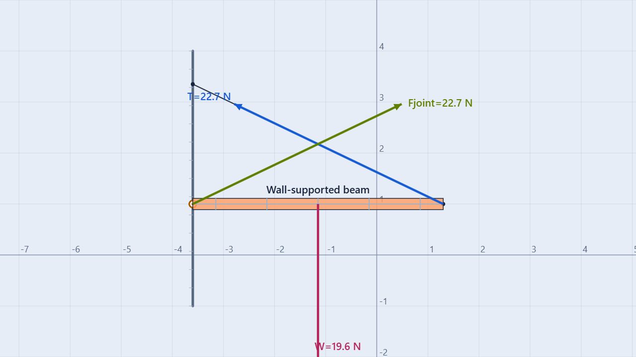
The prepared scene uses a 2.00 kg, 4.90 m horizontal beam. Its left end is pinned to a wall, and its right end is held by a support rope that runs up and left to the wall. The beam’s center of mass is at its midpoint. The default rope rises about 2.35 m over a horizontal run of 4.90 m, or roughly 25.6° above horizontal.
Keep fixed
Beam mass and length, gravity at 9.80 m/s², hinge location, and the beam’s horizontal orientation.
Change one variable
Change the rope’s wall attachment height or the beam mass. Measure rope tension and both hinge-reaction components after the system settles.
The beam is initially at rest, but it is not enough to check that it has zero angular acceleration. A complete static analysis needs Στ = 0, ΣFx = 0, and ΣFy = 0.
Build the model
Use the hinge as the torque pivot
Take counterclockwise torque as positive and sum torques about the left hinge. The hinge forces then produce no torque because their lever arm is zero. The beam’s weight acts downward at its center, while the rope’s vertical component acts upward at the right end:
Στhinge = T sinθ · L − mg · (L/2) = 0
T sinθ = mg/2
T = mg/(2 sinθ)
After finding the rope tension, balance the force components. The rope pulls left and up, so the hinge reaction points right and up in this setup:
ΣFx = Hx − T cosθ = 0
ΣFy = Hy + T sinθ − mg = 0
For a beam with only its own weight, the vertical hinge reaction is Hy = mg/2 regardless of rope angle. The horizontal hinge reaction changes with angle because the rope’s horizontal component changes.
Procedure
Measure tension and hinge reactions
- Load and inspect. Open Wall-Supported Beam Statics. Select the beam and record its mass, length, hinge position, and rope wall attachment. Confirm the beam is horizontal, the pivot is free, and friction is disabled.
- Measure the geometry. Use the rope endpoints to find its horizontal and vertical offsets. Calculate θ = tan⁻¹(Δy/|Δx|) and record the angle in degrees for reporting.
- Predict the rope tension. Use torque balance about the hinge: T = mg/(2 sinθ). Calculate the rope’s horizontal and vertical components.
- Run briefly. Press Run for a short interval, then pause. The beam should remain close to horizontal with angular velocity near zero. Open the Properties or Data panel to read rope tension and force components.
- Check both balances. Add the hinge and rope components with the beam’s weight. Separately calculate the clockwise and counterclockwise torques about the hinge. Report residuals rather than rounding each force before summing.
- Change one setting. Move the rope’s wall endpoint to create new angles, reset, and repeat. Keep mass and beam geometry fixed for the angle trial.
| Quantity | Calculation | Prediction |
|---|---|---|
| Beam weight | mg = 2.00 × 9.80 | 19.60 N downward |
| Rope angle | tan⁻¹(2.35/4.90) | 25.6° |
| Rope vertical component | mg/2 | 9.80 N upward |
| Rope tension | 9.80/sin(25.6°) | 22.7 N |
| Rope horizontal component | 22.7 cos(25.6°) | 20.4 N left |
| Hinge reaction | Hx = 20.4 N; Hy = 9.80 N | 20.4 N right, 9.80 N up |
The simulator may report slightly different rounded values because it resolves the rope constraint numerically. Use the displayed geometry and force values from the same paused frame when calculating residuals.
Worked example
Why a shallow rope needs more tension
For the default 25.6° rope angle, torque balance requires the rope’s vertical component to support half the beam’s weight:
T sin(25.6°) = 19.60/2 = 9.80 N
T = 9.80/sin(25.6°) ≈ 22.7 N
The rope pulls left with about 20.4 N, so the hinge must pull right with the same horizontal component. Vertically, the rope supplies 9.80 N of the 19.60 N weight and the hinge supplies the other 9.80 N. Both force components are required even though the beam looks horizontal.
Compare trials
Change the rope angle
Keep the 2.00 kg beam and 4.90 m length fixed. For a rope attached at the beam’s right end, the required vertical rope component stays at 9.80 N, but the total tension grows rapidly as the rope becomes more horizontal.
| Rope angle above horizontal | Tension (N) | Rope horizontal component (N) | Hinge horizontal reaction (N) |
|---|---|---|---|
| 15° | 37.9 | 36.6 left | 36.6 right |
| 25.6° | 22.7 | 20.4 left | 20.4 right |
| 40° | 15.3 | 11.7 left | 11.7 right |
| 60° | 11.3 | 5.66 left | 5.66 right |
The vertical hinge reaction remains 9.80 N in every ideal row. This is a useful check: angle changes the tension and horizontal reaction, while the torque-required vertical rope component stays fixed for this load placement.
Interpret the evidence
Use residuals to test equilibrium
Graph or record rope tension and beam angular velocity while the simulation runs. A well-balanced trial has a nearly constant tension and angular velocity near zero. If the beam oscillates, check whether the rope endpoint or beam angle was changed without allowing the system to settle.
Calculate three residuals from one paused frame:
Rx = Hx − T cosθ
Ry = Hy + T sinθ − mg
Rτ = T sinθ · L − mg · L/2
All three should be close to zero within the simulator’s rounding and numerical tolerance. A small angular velocity alone does not prove torque balance; use the torque residual as evidence.
Common misconceptions
Check the reasoning
Can I ignore the hinge force when taking torques?
You can omit it from the torque equation only because the hinge is the chosen pivot and its lever arm is zero. The hinge force still matters for the two force-balance equations.
Is the rope tension equal to the beam’s weight?
No. Only the rope’s vertical component balances half the beam’s weight in this geometry. The total tension is larger because the rope is angled.
Does a horizontal beam mean all vertical forces cancel in pairs?
No. The rope, hinge, and weight can share the vertical balance. What matters is their vector sum, not whether each force has an obvious partner.
Does zero angular velocity guarantee equilibrium?
No. An object can pass through zero angular velocity while accelerating rotationally. Static equilibrium requires both zero net torque and zero net force.
For teachers
Separate torque balance from force balance
Have students draw the beam’s free-body diagram and mark the hinge, center of mass, and rope attachment before calculating. Ask them to solve torque first, then use the result in the component force equations. This makes the role of the pivot and the nonvertical hinge reaction explicit.
Use four rope angles to plot tension versus 1/sinθ. The ideal relationship is linear. Add a point load at a new position as an extension and ask students which torque term changes. Review Free-Body Diagrams, Newton’s First Law and Equilibrium, and Teeter-Totter Rotational Equilibrium.
Physics reference: OpenStax, Physics, torque and static equilibrium. Learn about the educator behind the simulations on the BuildPhysics About page.